DC Battery Backup - Reef Aquarium
I recently started up a 91 gallon reef aquarium. One thing that is unique about an aquarium vs other pets, is just how dependent it is on stable electricity. A cat or dog or bird won't care too much if the power goes out for a day, but fish, coral and inverts will die without proper water circulation - some will die within an hour or two with no water movement.
The electrical grid is very stable here in south Alberta. However it has gone out once or twice in the past three years. If you care for your reef aquarium inhabitants (which you should if you are in the hobby), you will need to make sure they are provided for when the inevitable strikes.
There are several ways to provide backup power for your aquarium. From least elaborate / expensive to most, here is an incomplete list: 1. 24V battery and a simple relay to switch power. 2. Dedicated aquarium pump / wavemaker backup unit 3. Small computer UPS 4. Large computer UPS with extended runtime batteries 5. Gasoline generator 6. Whole house battery backup such as Tesla's
There are benefits and cons to these. For instance, the first three will only be able to power one or two pumps for at most a couple of hours. The dedicated aquarium pump backup unit might have an extended runtime as it throttles the speed of the pump, but it will only power one pump. A computer UPS is terrible at extended backup for small loads, so usually you get 1 - 4 hours. A large UPS with extended battery pack can provide backup power for more than just pumps, but it is a balance between power usage and runtime. I used to have an APC SMX750 with an extended battery pack and it could get 5.5 hours with everything on except chiller, heaters and lights. That UPS did cost about $2000. Generators can run indefinitely and are not too expensive but they are a hassle and noisy, and most would not switch over automatically so you need to be present when the power goes out. Whole house battery backup systems are great - but they are very expensive and costly to install.
As usual for me, I decided on building my own to improve on the limitations of off the shelf units. My goals were: 1. Run two wavemakers and the return pump 2. Have an extended capacity of at least 24 hours 3. Not be ridiculously expensive 4. Not be too large as I needed to hide it behind the aquarium cabinet 5. Not be noisy
Initially I tried a naïve solution:
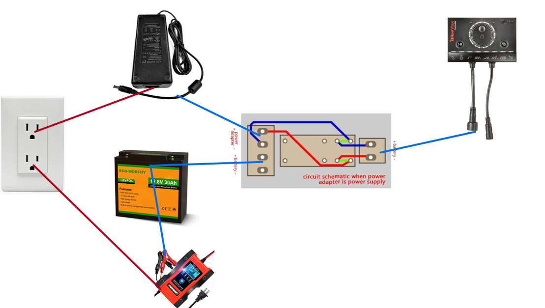
The idea was to have a simple DC backup relay from Amazon connected to the power supply of the wavemaker, and also to the 12V LiFePO4 battery, and then to the wavemaker's controller. If the AC power fails, the relay would switch over to the battery by opening its contacts. When the power comes back online, the relay will energise and engage, switching the power back to the AC supply. A battery charger would be connected to the battery to keep it trickle charged.
This idea ran into several issues: 1. The idea of keeping the trickle charger connected defeated the requirement for not being too large and not being noisy. So that had to go. 2. The relay was too slow - when it switched, the controller (being a microprocessor based controller) lost too much voltage to be able to stay on, so it rebooted and that caused the pump to stall and cut out. It did come back online but I did not want the return pump to turn off and on again as that messes with the water level in the overflow. Same happened when the power came back online - it would cut out for a couple of seconds.
For clarity, I have two ReefWave 45 RedSea gyre pumps and a RedSea ReefRun DC 5500 return pump I wanted to power - all microprocessor controlled.
So I went through a couple of design iterations and ended up with this circuit design:
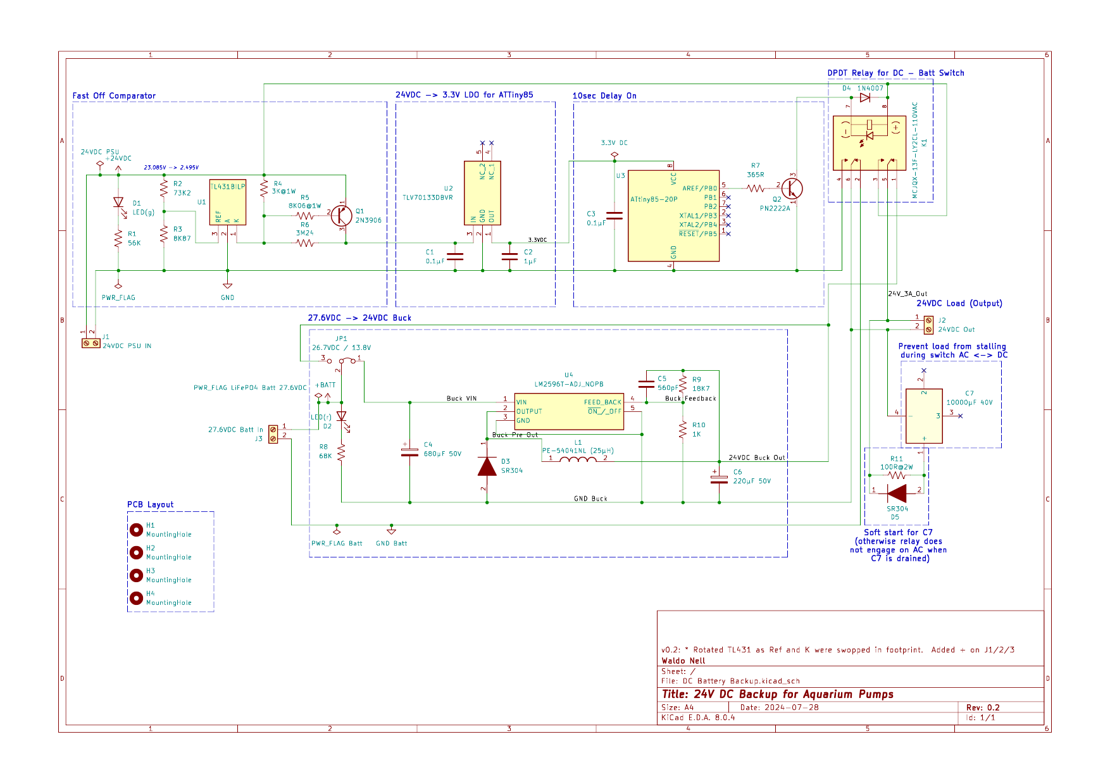
It works as follows. The system takes as input, a 24V DC input supply from the wavemaker/pump's AC power supply, as well as a 24V DC input supply from a 24V LiFePO4 battery, and produces a steady output of 24V DC. It is therefore inline between the AC power supply of the wavemaker/pump and the microcontroller.
In detail:
- The 24V DC input from the AC power supply goes through a first stage of a fast comparator circuit based off the TL431 chip. This chip is configured such that it acts as a fast off comparator circuit. Basically, if the input voltage (from the AC power supply) drops below 22.0V, it will immediately drop the output voltage of that stage down to 0. Without this circuit, the AC power supply drains slowly over the period of hundreds of milliseconds, and the voltage take a long time to drop below the release voltage of the relay's coil. This in turn would cause the relay not to switch over quickly enough and hence trigger the stalling of the pump. By cutting the AC source power when it reaches 22.0V, it switches much faster to the battery supply. The Q1 output PNP transistor turns off when the cathode of the TL431 goes low, and that in turn turns off the TLV70133 LDO that powers the microchip of the next stage.
- A second stage is based on a digital microcontroller, the ATTiny85, which has a very simple program: at boot, sleep for 10 seconds then turn an output pin high. This microcontroller needs a 3.3V DC power supply, therefore I have a TLV70133 based LDO to convert 24V to 3.3V. This output delay is to resolve the "AC power back on" issue, where the system would cut out if I cut over to the AC supply immediately when the power comes back online. I found that allowing the capacitors to fully charge and the power supply to stabilise first, there was no cutout any longer when the power returned. Why 10 seconds? 2 seconds would probably have worked but I thought of brownouts and it did not really make a difference to leave the battery connected for a couple more seconds. This pin that goes high drives a PN2222 NPN transistor that in turn switches on a DPDT 24V relay.
- This relay is at the heart of the circuit. It switches between the AC based 24V DC supply and the battery based 24V DC supply. It has a 15ms release time which is plenty fast.
- There was one issue however - a 24V LiFePO4 battery, when fully charged, does not output 24V. It outputs 27.6V DC. I was worried that this exceeded the design specifications of the wavemaker/pump microcontroller which assumes a 24.0V DC supply. I therefore initially bought one of those cheap LM2596 based DC-DC buck converters on Amazon. It worked, however I found out how terrible the performance is and that it was made from knockoff components. Also, it got very hot as it was technically only rated for 1A continuous, anything higher and the specs said it needed external cooling. I was drawing 1 - 1.25A, and this worried me. I therefore built my own LM2596 based buck converter. I got an authentic LM2596 regulator from Mouser, as well as proper Nichicon caps and an inductor, large schottky diode etc. to complete the reference design circuit. I even added a proper heatsink to the regulator so I should be fine up to 3A.
- As I also initially purchased a 12V LiFePO4 battery (the wavemakers work fine on 12V, the return pump does not that is why I later got the 24V battery), and I did not want to design multiple circuits, I added a jumper to allow this buck converter to be bypassed for the 12V battery.
- One last issue I ran into was that even with all this logic there was still a problem during switching. To fix this I added a huge 10mF 40V capacitor at the output of the circuit. This had ample reserve to provide power during the 15 - 20ms the relay takes to switch.
- One last problem remained - when the unit was turned on from being completely off, it would not start up on AC. The relay would click on and off rapidly. The problem was identified to be the large power draw from the 10mF capacitor when booting the circuit, causing the supply voltage from the AC adaptor to drop enough to cause the relay to disengage - remember, a small drop of 2V would trigger the fast off comparator and that would kill the power to the relay. I had to figure out a way to slow the initial charging of the capacitor. There are many ways to do this, but the most simple and still effective way was a simple resistor and diode in parallel to the capacitor. The resistor slowed down the maximum inrush current to the capacitor during startup, and the diode provided a low impedance path for current flowing from the capacitor into the load. This fixed the voltage drop on the AC power supply during cold startup.
With the circuit designed and parts ordered from Mouser, I built it on a breadboard. The initial PoC worked great, so I moved on to the next two challenges.
I needed this to be neat. I planned on building three copies of this circuit, one 24V - 24V for the return pump, one 24V - 24V for one wavemaker and one 24V/12V - 12V for the other wavemaker. The first two would be powered by the 24V 100Ah LiFePO4 battery, and the other by the 12V 30Ah battery. You could ask why I am not powering the first two with one circuit, but I wanted to stay well within the limits of my power draw and have them independent for more flexibility.
The best way to make a circuit neat and reliable is to custom build your own PCB. That is exactly what I did using KiCAD:
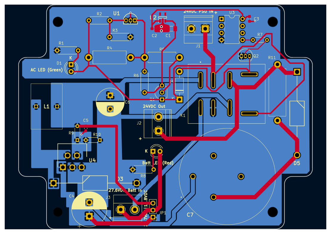
This layout was based on a PCB sized to fit a project box I found on Amazon. It was the smallest box I could find that would be able to contain all the different components. Some careful routing later, I had a design that seemed to fit. I sent this off to JLCPCB to have 5 copies manufactured. It was only a week before I took delivery of them.
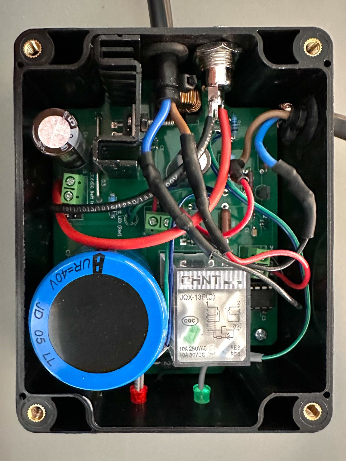
The project box needed to be drilled and prepared for the PCB and DC input / output sockets. Once done I had this circuit:
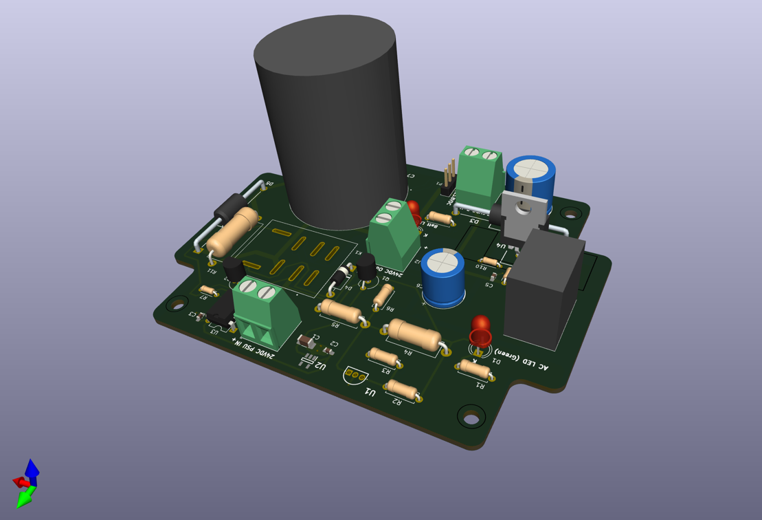
And here is the finished product:
I have tested it and it works fine from a cold start, works fine when switching from AC to DC, and when AC comes back online, after 10 seconds it switches back to the AC source with no interruption.
This is by far not the cheapest or easiest solution. If you can live with the cutoff when it fails over from AC to DC and vice versa, then a simple relay switch and 24V battery would suffice. If you want the circuit to operate without interruption, something like what I have designed would work better. Also, if you do not have a 27.6V and 24.0V source that needed to work together, the double diode based solution would be the easiest - removing the need for a relay.
Another consideration for my design is that my pumps and wavemakers are DC, not AC. This is important, as using a UPS requires additional circuitry (an inverter) to up convert the 12V of the internal battery to 120V AC as that is what a UPS outputs. This is then down converted again to 24V by the AC adapter of the pump, which wastes energy and runtime. By bypassing this needless 12VDC -> 120VAC -> 24VDC conversion, the battery's runtime is dramatically extended. the downside is that my solution cannot power lights or heaters.
A simple calculation yields:
12V LiFePO4 30Ah: 1 x 15W Wavemaker @ 12V => (12V x 30Ah) / 15W = 24 hours.
24V LiFePO4 100Ah: 1 x 15W Wavemaker @ 24V + 1 x 30W Return pump => (24V x 100Ah) / (15W + 30W) = 53 hours.
Of course, there is some extra power dissipated in my circuit, but that is insignificant relative to the load. Also, I made sure to not have the 27.8V -> 24V buck converter draw any power when the unit is on AC, so as to prolong the battery charge when not providing current.
I will have to top up the charge on the batteries once a while, and that is fine. I decided not to permanently hook up the charger as it is a huge GeniusPro25 Noco charger.
Do keep in mind that although I have an education in electrical engineering, I am by no means a professional practitioner in this field and am not claiming that my design is correct or even safe. I would also add some fuses to the design to make sure the battery is protected. So if you want to copy this design, feel free to do so but do so at your own risk. You have been warned.